Oak Hill Marine Design
Naval Architecture ~ Marine Design ~ Manual and Computer Drafting Services
Ferry - Lofting and Creation of Parts
In the summer of 2010, Oak Hill Marine Design was again hired by Bay Marine, Inc., in Barrington, Rhode Island, http://www.baymarine.us/ to provide CAD data for the detail design of a 90’ ferry.
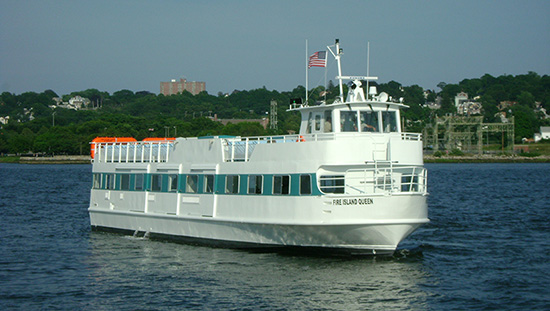 Fire Island Queen - The finished vessel shortly after launch. (Photo courtesy of Gladding-Hearn Shipbuilding)
This vessel had a difficult hull to model. There was a lot of flare in the bow sections, a flat bar stem that transitioned into conical plate above the waterline, and a narrow chine that disappeared into the hull forward of amidships. Triple propellers in shallow tunnels added to the complexity.
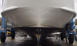
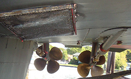 Bow Plating, and Prop Tunnels Aft
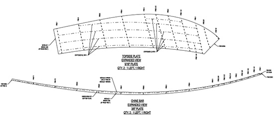
The hull lines were only available on a paper. We scaled the basic curves off the drawing and created them in 3D using AeroHydro’s MultiSurf software. We then modeled the hull, chine, skeg, fore deck, and main deck to fit these curves. The bow plating was modeled as a compound curved surface, with the expectation that it would later be broken into three separate plates for installation. As can be seen in the final drawing of the expanded bow plates, the shipyard chose to work with the plate as a single piece and trim it as needed when it was installed.
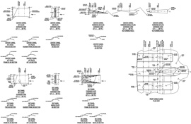
 Module 1 Plates
Some design and manufacturing details were worked out during the initial hull modeling, including the aforementioned chine and the guard pipe. The latter was modeled at three different locations so that the shipyard could evaluate the construction advantages and disadvantages. MultiSurf’s relational geometry made it easy to model the pipe section first, then relocate it without losing any of the original section detail, or the connections with hull and deck plates.
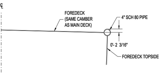 Fore Deck Guard Pipe Options
Once we were satisfied that the hull and deck lines matched the Lines Plan with a reasonable degree of accuracy, we created a preliminary set of lines for Bay Marine to review. Even before these were approved we began to model the hull’s internal structure. Again, this was made practical by MultiSurf’s relational geometry. We were able to model structural members in approximate locations, based on the preliminary design, and then, with simple edits, move them to their final locations. The structural detailing included transverse bulkheads and frames of differing thicknesses, longitudinal stiffeners of varying sections, bulkheads, and girders.
From the final hull and deck model we exported expanded plate shapes and structural sections. Bay Marine detailed the former for CNC cutting by the builder, and used the latter in construction drawings.
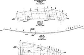
 Bow Plating, and Tunnel Plates
As usual, we created a wireframe model from the hull model for hydrostatic analysis, and offset tables of the hull and superstructure for the builder’s use when erecting the frames.